| |


Next: Microcontroller Module (Pbus and
Up: Control Board
Previous: Transport Control Module
Contents
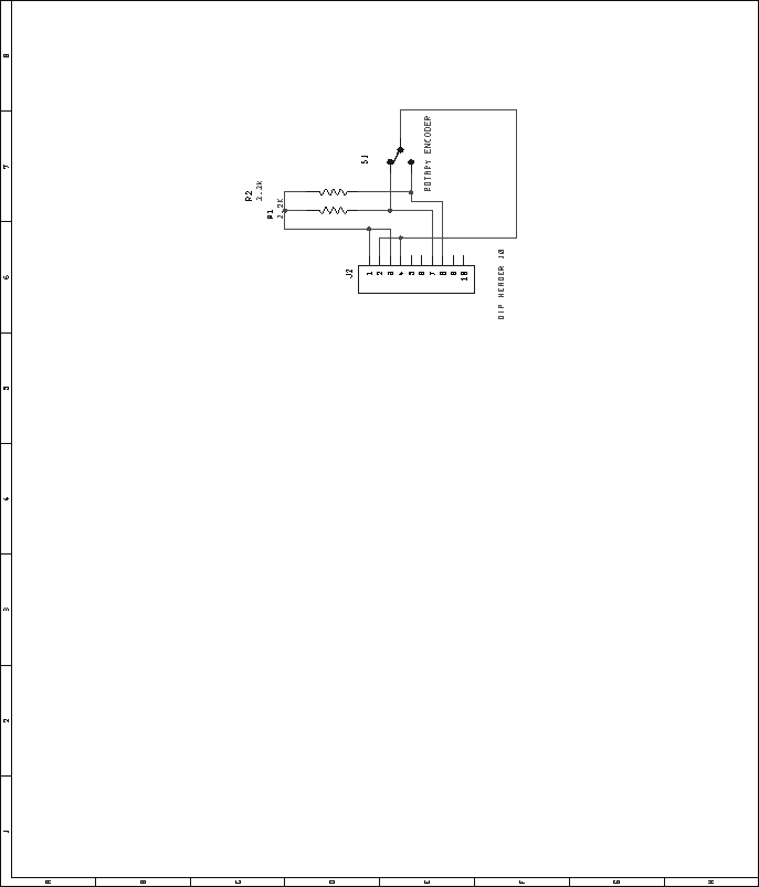
As previously mentioned, the rotary encoder present in the universal
user interface section connects to the transport control section.
Figure 54 shows this connection and the associated
circuit.
Figure 54:
Universal user interface submodule, rotary encoder schematic. This
circuit connects to the transport control encoder interface.
 |
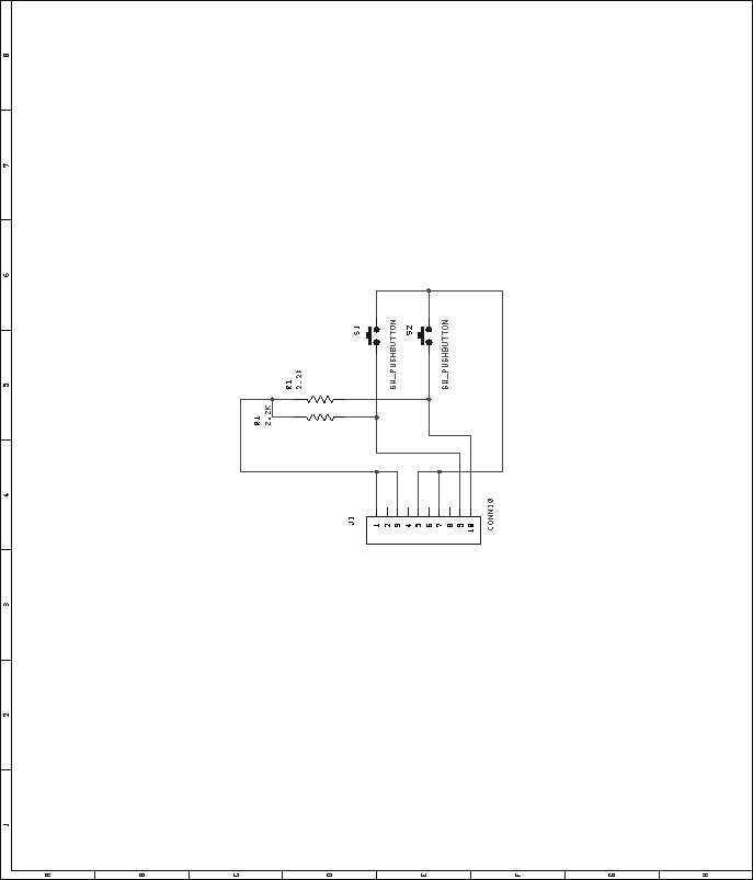
The universal user interface module also contains a pair of pushbutton
switches. These switches interface to the output assign board, as
shown in figure 55.
Figure 55:
Universal user interface submodule, momentary pushbutton interface
schematic. This circuit connects to the output assign button interface.
 |
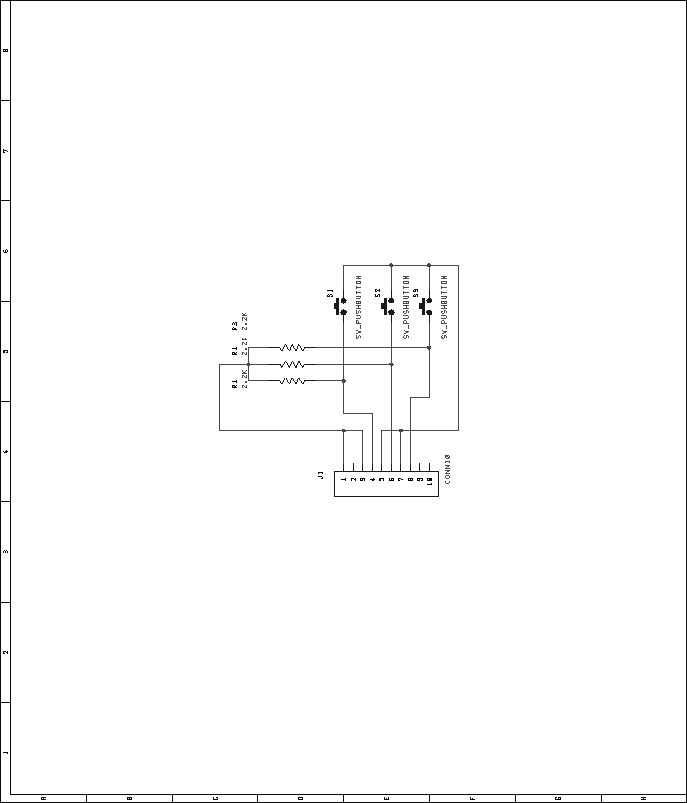
The cue stack control section contains three pushbutton switches that
interface to the output assign module. Figure 56 shows
this connection.
Figure 56:
Cue stack submodule, momentary pushbutton interface schematic.
This circuit connects to the output assign button interface.
 |


Next: Microcontroller Module (Pbus and
Up: Control Board
Previous: Transport Control Module
Contents
Steve Richardson
2000-07-06
|
Table of Contents
![[PDF]](/~prefect/images/pdficonsmall.gif) [Whole document in PDF 1.9MB]
[Whole document in PDF 1.9MB]
[more photos and information]
|


