|

|
DACS: Audio Input Module | 
|
|
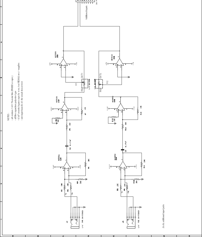
Next: Audio Mix Module Up: Mixer Unit Previous: Mixer Unit Contents Audio Input ModuleThis is the original design for the audio input module. Through clever use of a normalling jack, either balanced or unbalanced signals may be input. Capacitive coupling is used to remove any residual DC offset from the input. A trim stage, based on the Dallas Semiconductor DS1800 digital potentiometer, provides audio trim capabilities. Unfortunately, when this circuit was designed (and later fabricated), it was not known that the DS1800 is not a bipolar device, thus it is inappropriate in this situation. For the prototype, this functionality was sacrificed, but a stock of National Semiconductor LM1972 bipolar digital volume controls was obtained. At some point in the future, the circuit will be redesigned using this part.Steve Richardson 2000-07-06 |
Table of Contents
| |
